The variable diameter pulley CVT
A CVT transmission consists of a driving shaft and a driven shaft, each of which has a pulley splined onto it. Each pulley comprises two conical sheaves that face each other. A metallic pushbelt runs in the V-groove between the two conical sheaves of each pulley.
The pushbelt (See glossary) forms the link between the driving and the driven shaft, transmitting the drive power by means of shear force from the engine to the wheels. The transmitted shear force makes the pushbelt as strong as a steel rod, thereby enabling torques of over 400 Nm to be transmitted. Pushbelt is made of hundreds of specially pressed steel elements which are strung together between two rings made of layers of high-alloy steel. This design makes the pushbelt flexible and at the same time strong enough to transmit torque.
Variable pitch radius principle
One sheave of each pulley can slide along each its shaft, continuously adjusting the pitch radius of the pushbelt and, in turn, the transmission ratio. The variable distance between the sheaves thus offers infinitely variable ratios. The continuously variable transmission ratio enhances ride comfort and dynamism.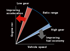
Optimal engine operation
The special CVT transmission mechanism and electronic control provide an optimal balance between required torque and engine speed, thus allowing the engine to operate as efficiently as possible at all times. The gear ratio range (See glossary) from low to high gear can be high compared to manual gearbox, attaining a final gear reduction ratio of about 6, thanks to pulley and steel belt improvements and the use of high performance ATF (Automatic Transmission Fluid). With a wide ratio spread and highly precise control, the CVT delivers improved acceleration and fuel economy. However, those features have to be balanced with the increase in friction losses due to contact between pushbelt and puleys. Indeed, gain of having optimal engine operating points is lowered by greater frictions within the transmission system.
Toroidal CVT
The principle of toroidal CVT is the same as variable diameter pulley CVT. The engine’s power is transmitted to an input disc the rotational motion of which is transferred to the power rollers and then from the rollers to an output disc. By changing the tilt of the power rollers continuously, the toroidal CVT executes smooth and continuous gear ratio changes. The size of the circle traced by the contact point between the input disc and the power rollers and that of the circle traced by the contact point between the power rollers and the output disc vary according to the tilt of the power rollers. The ratio of the sizes of the circles corresponds to the ratio of the rotational speeds of the input and output discs, which is equal to the gear ratio.When the circle on the output disc side is larger, the output disc rotates faster than the input disc. This corresponds to the low gear range of a conventional transmission (Low in the diagram below). Conversely, when the circle on the output disc side is smaller, the output disc rotates faster than the input disc. This corresponds to the top gear range of a conventional gearbox (High in the diagram below).


