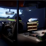
Before automotive OEMs purchase a new sensor system, they want to see a real-time prototype of the sensor working in a vehicle environment so as to evaluate its performance and potentially modify its specifications. For example, Hella (A lighting and electronic components and systems supplier company) often needs to demonstrate an early version of sensors, which usually incorporate algorithms and logic implemented on an FPGA or microprocessor. To meet this requirement, Hella engineers use a custom rapid control prototyping platform and Model-Based Design to build real-time prototypes of new designs early in the development process. The real-time prototype (known at Hella as an A-sample) serves both as a proof of concept and as a living specification throughout development.
Instead of waiting up to two years for an ASIC implementation, they can produce an A-sample that incorporates about 80% of the final product’s functionality in a few months. The A-sample enables to work with the OEM early in development to refine the sensor’s functionality and evaluate the code size, partitioning of modules, and hardware requirements. Testing groups use the A-sample to set up the test environment and test suites so that testing can start as soon as a production sample, implemented as an ASIC or on a microprocessor, is ready.
Creating a Flexible Prototyping Environment
Hella engineers built the Hella Fahrzeugkomponenten GmbH Rapid Control Prototyping (HFK RCP) unit because commercially available alternatives lack the flexibility they need. Most off-the-shelf prototyping systems only support ECU software development, but a sensor design may also include VHDL® code and discrete electronic components. A second limitation of a commercial system is the fixed set of interfaces it provides. At Hella, they must support a wide array of communications protocols and interface hardware, including SPI, I2C, LIN, XCP, CAN, and SENT.
With Model-Based Design and custom prototyping environment they can add new interfaces, protocols, and capabilities as needed. Hella can target microprocessors and FPGAs as they develop specifications and use the prototyping environment to extend or enhance algorithms already implemented on a production processor.
From Requirements to Design
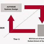
The Hella’s development process, which follows the V-model, consists of five main steps: requirements analysis, algorithm design, production code generation, code verification, and testing. In the requirements analysis phase, Hella’s system engineers work with the customer to define system requirements in IBM®Rational® DOORS®. They then create an initial model of the design in Simulink® (Figure 1).
They use Simulink Verification and Validation™ to map requirements in DOORS to elements of the model, enabling bidirectional traceability of requirements.
When creating the model, they use Model Advisor to ensure that they are adhering to MathWorks Automotive Advisory Board (MAAB) algorithm modeling guidelines. They also include Model Advisor checks based on the guidelines developed internally.
For early functional verification of the initial floating-point design, engineers run simulations in Simulink, stimulating the model with test data gathered from a similar sensor or generated with a Simulink block. After these model-in-the-loop tests, the model coverage reports created with Simulink Verification and Validation are evaluated to identify untested elements in the model, updating the tests as needed to increase coverage.
In preparation for testing on the rapid prototyping platform, they model the communication interface that will enable the sensor algorithms to run in a vehicle. Working with MathWorks consultants, Hella has developed a local interconnect networking (LIN) blockset for Simulink, which has enabled them to expand the capabilities of prototyping system to support LIN.
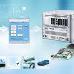
From Model to Prototype
After an internal design review of the model, they move the design into the HFK RCP unit (Figure 2). HFK RCP supports a broad range of design configurations with a standardized set of components that include TI’s C2000™ microprocessor, a Xilinx® FPGA, and connectors for automotive buses and sensors, as well as an area for discrete electronic components.
For designs that target a microprocessor, Hella SW engineers use Embedded Coder™ to generate code from Simulink model and deploy it to the TI C2000 processor on the HFK RCP unit. If all or part of the design requires an FPGA, they use HDL Coder™ to generate VHDL code from the model for deployment on the Xilinx FPGA.
© 2014 The MathWorks, Inc. MATLAB and Simulink are registered trademarks of The MathWorks, Inc. See www.mathworks.com/trademarks for a list of additional trademarks. Other product or brand names may be trademarks or registered trademarks of their respective holders.
This article has been reprinted with permission from MathWorks and Hella
Romain’s opinion:
This way of working enables early detection of issues and test campaign optimization which means big savings. Do you think this methodology is applied systematically? Are there any pre-processing and post-processing scripts together with this Model-Based Design tool, to ease engineers’ work? How do they handle collaborative work at Hella? What about Models and Data configuration management?