A cordierite perspective
The cordierite is issued from sedimentary rocks. Deposits can be found in Sri Lanka, India, Burma, Madagascar, USA and Canada. It has a high thermal resistance and is a relatively strong material. However, it has a high coefficient of thermal expansion (CTE) and a relatively low density. Cordierite is a high volume through-put via low cost extrusion or dye-pressing processes. It is used in electrical insulation domain, high performance resistors, burner tubes, and of course exhaust catalysts supports and filters.
Cordierite ceramic honeycomb based catalytic converters
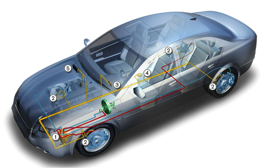
The first application of cordierite in automotive industry was the usage of cordierite ceramics in the catalytic converters from the middle of seventies. These catalytic convertors are wall through chemical reactors which are integrated in the exhaust pipe. They are used to convert pollutants like CO, HC and NOx in some particular cases.")
How does a catalytic converter work?
A catalytic converter is composed of a substrate, the washcoat, catalysts, the mat and the can.")
The substrate is a ceramic honeycomb-like which provides surface area for the catalyst and where the washcoat is deposed.The washcoat is a deposit which increases the effective area of the substrate. It helps controlling the catalysis thanks to its properties and facilitates the deposit of catalyst onto the surface.The catalyst is in general a precious metal which catalyzes the conversion of pollutants into harmless gases. It is applied to the washcoated substrate through a chemical process.The mat is wrapped around substrate and provides thermal insulation, protection against mechanical shocks and vehicle vibrations.The can is a metal package that encases the substrates and its mat.
Catalyst substrate for air pollution control
The ceramic monolith used in converters has a pore structure (around 3 to 4 µm pores) which allows both mechanical and chemical link to the washcoat. It offers a high surface area for washcoat deposit like Al2O3 and can be further impregnated with a catalytic component such as Platinum.
Key manufacturing elements
The manufacturing process is the following:
1. Raw material processing
Material is delivered to the manufacturing site by trucks. It is weighed and checked by manufacture laboratory. Then materials are mixed into a batch which is mixed with water and conveyed to extrusion.
2. Forming and drying
The cell geometry is formed by extrusion of the batch material. The cell density, shape, and wall thickness are formed here. It is then dried thanks to microwave.
3. Cutting and loading
Pieces are cut to size and cleaned. A process control is performed at this step to ensure parts conformity. Pieces are then loaded in a kiln (thermally insulated chamber).
4. Firing
A firing is performed according to a precise time-temperature cycle.
5. Finishing and shipping
The cordierite substrates are then packaged and shipped to customer’s assembly site.
Macro-cellular design and performance data
Monolith porous ceramics as catalyst substrates for air pollution control
The main advantage of monolithic material is that it offers a relatively low back pressure compared to pellet-shaped catalysts. It is important in a fuel economy point of view as the engine will need less work to evacuate burned gas.
Then it offers a higher surface area than conventional pellet-shaped catalysts. This allows to have more washcoat area and then better conversion efficiency.The monolith properties can hence be tailored for optimum catalyst and reactor performance:
Substrate geometric considerations
The main geometric characteristics are defined as follows: The cell density is often defined in cells per square inch (cpsi) and the wall thickness in 10^-3 inch. A substrate typical dimension definition is N/w like 400/4 or 900/2.Having a higher cell density and lower wall thickness allows a better conversion of pollutants and a decreased light-off temperature:
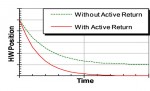
In order to test efficiency of different substrates, manufacturers perform vehicle tests on homologated cycles.To do so, a standard engine is chosen as an exhaust gas generator. The engine is operated over a given cycle (e.g. FTP cycle). The tested substrate is mounted in the exhaust line, coated with a constant amount of Platinum Group Metals (PGM). Then, 3 runs are performed with overnight soak and cold start. Both continuous measurement and bag sampling are performed and analyzed. Typical analysis result is a graph representing accumulated HC versus time for different substrate:
Thermal shock and erosion considerations
Thermal induced stress
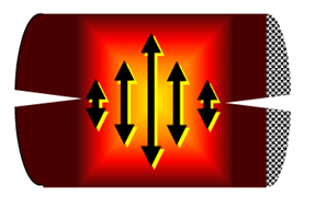
Thermal stress is defined by a sudden change of temperature. A fracture can occur when thermal stress exceeds strength of the body.
Thermal stress is due to thermal expansion which is defined by the relative length increase compared to the initial length of the body (∆L/L). The hotter the region will expand more than the cooler region of the body. This difference of expansion is called thermal strain and will cause stress in the cooler region:

There exists two kinds of cracking due to thermal expansion. The first one called ring-off cracking happens when the center of substrate is hotter than skin. The center hence expands in axial direction more than the skin. The latter is then in tension and if tension exceeds axial strength, ring-off cracking appears around the circumference.
 The second kind of thermal crack is the face cracking. It appears when the center is hotter than the end faces. The hot center expands in radial direction more than the end faces. Then faces are in tension and if tension exceeds radial strength, a face cracking appears.
In order to estimate the thermal stress and temperature at failure, several physical values are taken into account such as the CTE curve (Coefficient of Thermal Expansion), E (Elastic modulus), T1, T2 and MOR (Modulus of Rupture).Let’s approximate the honeycomb of a catalyst as solid cylinder of an infinite length, where the interior temperature is equal to T2 and surface temperature is equal to T1. Simplified treatment of stress equation gives:
 Axial stress ≈ ET1(∆L/LT2-∆L/LT1), which is equivalent to:
Axial stress ≈ ET1(CTET1 to T2)(T2-T1)
Once the predicted axial stress is computed, the ”stress parameter” is defined in order to assess the thermal durability of a DPF during high temperature regeneration for example:
SP≡E500°C(∆L/L500-900°C)
This stress parameter enables to estimate the probability of survival in such conditions by considering the Modulus Of Rupture (MOR). Indeed, the ratio SP/MOR is proportional to the probability of survival of the substrate. In the same manner, failure occurs when MOR is equal to stress.
Erosion
The erosion phenomenon is mainly due to presence of particulates in the exhaust. It decreases while the temperature increases because substrate MOR increases at higher temperatures (>400°C).
For assessing the erosion phenomenon, a substrate front face is “sand blasted” with e.g. 100 g SiC particles in a lab. The aim is to determine the footprint left by the erosion and the amount of cell plugged by SiC particles. If particles are smaller than channels, the flow distribution will be uniform and the erosion footprint will only depend on the flow distribution (left). Whereas if the particles are larger than the channels, there will be cell plugging and then uneven erosion leading to uneven flow distribution (right).
Conclusion
The utility of the macro-cellular product is further enhanced via process flexibility to control key macro-structural (design) attributes. Critical attribute is resistance to stress and erosion which represents the durability of the substrate and then durability of the catalyst or filter.
Source: Corning
Romain Nicolas opinion:
The cordierite substrate is a pretty efficient filtration device and it is also inexpensive. However, its melting temperature is relatively low compared to Silicon Carbide (SiC) substrates which can be an issue when it faces uncontrolled regenerations. How do you think manufacturers deal with the tradeoff between cost and risk of melting when choosing either Cordierite or SiC substrates? Do you foresee any technologic breakthrough concerning after-treatment substrates?