OBD definition
“On Board Diagnostic” is a comprehensive electronic system, which detects exhaust emission related failures in passenger vehicles, light duty trucks and since some years also in heavy duty vehicles, which run on combustion engines. These types of engines produce toxic exhaust emissions like HC, CO, NOx and soot. The amount of these emissions is regulated by law in many countries (see emissions regulation map). To fulfill these legal requirements, complex exhaust emission control and cleaning systems are installed by OEMs. These systems and the related components have to be monitored by a so called On Board Diagnostic system.
The OBD laws require that all components and subsystems which have an emission impact and which are connected to an Engine Control Unit (ECU) need to be monitored and diagnosed. The components can be divided into:
- Sensors: O2 sensor, temperature sensors, pressure sensors, etc.
- Actuators: Fuel injectors, ignition coils, throttle blades, cam phasers, EGR valve, etc.
On the system side, several subsystems have to be monitored such as a malfunction of a complete subsystem which leads to a certain emission increase. Such subsystems are:
- Fuel Injection System
- Ignition system
- Exhaust gas cleaning system
- Canister purge system
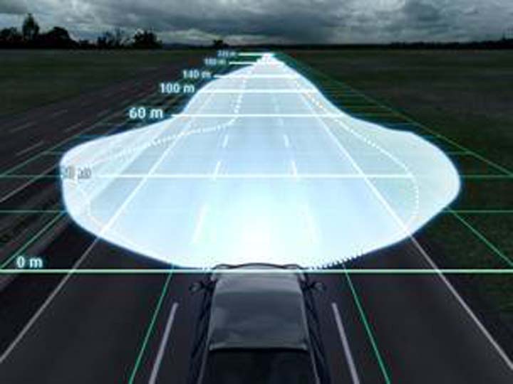
The following picture gives an overview of a complete engine management system with all related components connected to a central ECU.
")
The law requires only diagnostics on components which lead to an increase of exhaust emissions. However, failures of components which lead to a degradation of the OBD diagnostic system have also to be detected.
As an example, the malfunction of the vehicle speed sensor has no or minor impact on emissions. The sensor is used by ECU to optimize several driveability functions which have normally no emission impact. But this sensor is also used by the ECU to trigger a so called “rough-road detection” algorithm. And this algorithm is used by the misfire diagnostics. So if the sensor fails, the rough road detection cannot occur, which might inhibits the misfire diagnostic. In this case, the sensor failure gets to an emission impact because the misfire diagnostic is used to detect missing combustion events (which lead to high HC emissions).
The progress in electronics makes it possible to diagnose all or most of the sensors and actuators connected to an engine control unit. A current Engine Management System (EMS) for a 4 cylinder gasoline engine includes more than 25 sensors and about 30 to 35 actuators. A modern direct injection EMS tends to have 50% more sensors and actuators.
All these components have to be diagnosed electrically, some of them also against rationality failures. In addition, drive-by-wire systems as electronic throttle control require enhanced diagnostic functionality for safety reasons to avoid i.e. unwanted acceleration. Although these diagnostics are not part of the legally required OBD, they fall under the OBD functions and related algorithms.
So overall in decent EMS software, 40% of the code is diagnostic related. A current EMS has about 9000 – 12000 calibration values and tables, which means that around 3500 – 4500 diagnostic related parameters are calibrated in every vehicle. These numbers underline the importance of current OBD systems.
OBD Legal requirements
OBD II and EOBD
OBD II is the legal requirement in USA since 1997, whereas EOBD is the legal requirement in Europe since 2000.
The following gives a summary of the legal requirements in the USA and in Europe.
- Detection of electrical failures of emission related components
- Detection of plausibility failures of emission related components
- Actuators faults
- Detection of degradation of emission related components and subsystems:
- Catalytic converter (HC, CO and NOx)
- 02 sensors
- Particulate filters (In Europe)
- Fuel system
- Misfire
- Evaporative system leakage detection (In USA)
- Evaporative system electrical diagnostic (In Europe)
- Crank case ventilation (In USA)
- A/C refrigerant loss
- Secondary air system (In USA)
- Coolant thermostat (In USA)
Fail criteria, MIL illumination, default modes
In case of failure, the following actions have to happen:
Highest priority for failures which can damage the engine or create a safety risk for the driver and therefore require a default mode: Type A failures
Actions:
- Immediate MIL (Malfunction Indicator Light) upon detection of failure.
- Default mode, i.e. a load or speed limitation, a default position of actuators, …
Examples of type A failures are catalyst damaging, ignition coils failure, Electronic throttle control failure …
Lower priority for failures which cause an exceeding of the OBD II/EOBD emission levels: Type B failures.
Actions:
- MIL illumination after or during the 2nd consecutive driving cycle where the failure is detected.
- A default mode can be introduced if possible. An example of a default mode can be the usage of a model of the coolant temperature when the coolant sensor fails.
Detection limits for OBD II
The American OBD defines detection limits in percent of emission limits. So lower emission limits lead to lower OBD limits, which makes it necessary to have robust OBD II detection algorithms. It needs to be able to detect smaller and smaller failures while ensuring that no false detection is happening, which would lead to a mistrust of the end used to the OBD system.
The definition of OBD II emission failure detection is described in the following diagram:

If a failure of a component or system would cause an increase of the vehicle emissions above the OBDII limits, the MIL has to be turned on.
During the certification process, the legal authorities may require that a demonstration of the failure or degradation of certain components is carried out. During this demonstration, the OEM has to proof that the MIL is turned on before the OBDII emission limits are exceeded in an emission test.
Detection limits for EOBD
The EOBD legislation defines the EOBD thresholds as absolute emission limits. Compared to the US legal requirements, the intention of the EOBD is more laying on robust detection, because the EOBD emissions limits are in general higher than the US limits. The negative impact is that a higher tolerance is given to components and subsystems before a failure has to be detected.
Nevertheless, Euro 6 OBD legislation lower the EOBD emission limits, hence the definition of a “defective” part.
The definition of an EOBD emission failure detection is described in the following diagram:

The same certification process applies as for OBD II.
MIL illumination and failure deletion
The MIL, once it has been turned on, might be turned off in the following cases:
- After the 3rd consecutive driving cycle with no failure detection
- After a service command in the garage
The failure which is stored in the ECU (Freeze frame) can be erased after:
- 40 driving cycles without fail report
- A service command in the garage
Romain’s opinion:
OBD is getting more and more importance and is more and more difficult to satisfy. Do you think there are controls for vehicles that are in use since some years? Will OBD legislation be applied in emerging countries in the same extend as in developed ones?


Pingback: Finding the Best OBD Diagnostic Tool: Buying Guide and Reviews - Decked Out Ride